
After looking into the Curatio hand mapping solution, It was clear that some aspects of the implementation could be potentially useful to the development of HandMap. In particular it would seem that a Scale-invariant feature transform (SIFT) method was used to generate a mesh of points from the 32 cameras utilized in the design.
Scale-invariant feature transform or more commonly referred to as SIFT is a method for matching features across different images. These matches can be used to get scale, rotation, illumination and viewport location of an object of interest in a series of photographs or video frames.
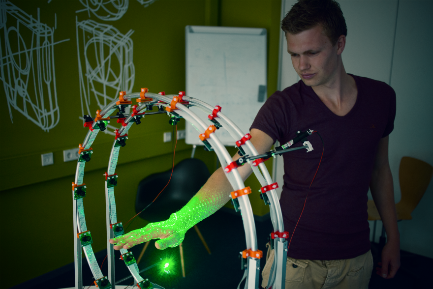
This idea was most likely implemented in the Curatio, as it can use its many cameras to capture the same object from a number of sides to produce a mesh output used for generating a 3D replica of a hand (or object).
Before implementing the SIFT method for HandMap it was important to understand what kinds of computational requirements are needed to generate the 3D mesh. Luckily there was a simple implementation with a GUI called VisualSFM that allows for simple SIFT structural calculations and visualizations.
Following the instructions outlined on the VisualSFM documentation page the set up of the platform on Windows was simple enough.
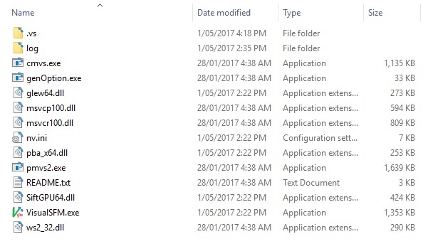
The CMVS-PMVS binaries for Windows also need to be included in the directory of the VisualSFM folder. These can be obtained from the CMVS-PMVS git repo. The binaries for your system can just be dropped in the root directory.
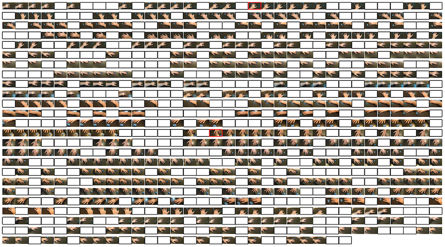
In order to test the SIFT method a number of images was required of an object to scan. The quality of the images used directly influences the ratio of how many images you’ll need to get a reasonably successful result. In order to test, a video was taken of my hand that encompassed a number of different angles.
This video was then converted into 884 still frame images using the following code:
import cv2

vidcap = cv2.VideoCapture('in-video.mp4')
success,image = vidcap.read()
count = 0
success = True
while success:
    success,image = vidcap.read()
    print('Read a new frame: ', success)
    cv2.imwrite("images/frame%d.jpg" % count, image) # save frame as JPEG file
    count += 1
Then using the VisualSFM software, the images were loaded into the preview pane by selecting File -> Open+MultiImages
Next click the Match the Images button. It should be the four arrows pointing outward in the menu bar (item 2 in the following image). This process should run quickly. The run the Sparse reconstruction by pressing item 3 in the menu.
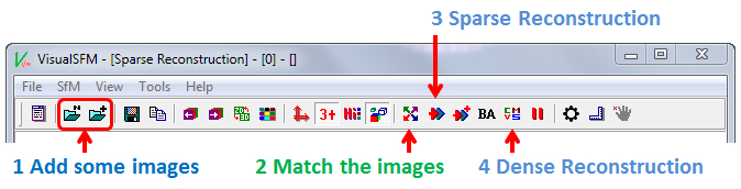
Depending on the number of source images, this process could take a while. In the example here, the 884 source images took roughly 20 minutes to complete the initial map.
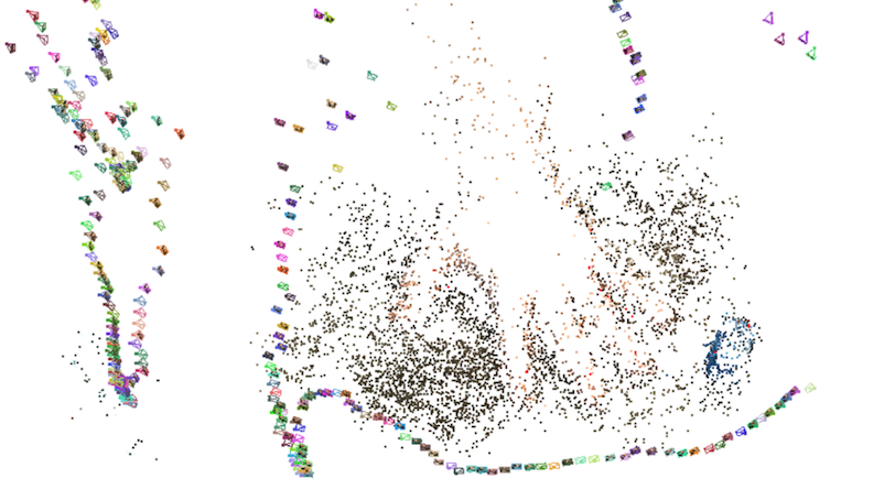
Note that the coloured pyramids represent a calculated position and rotation of a viewport (where the photo was taken from relative to the object).
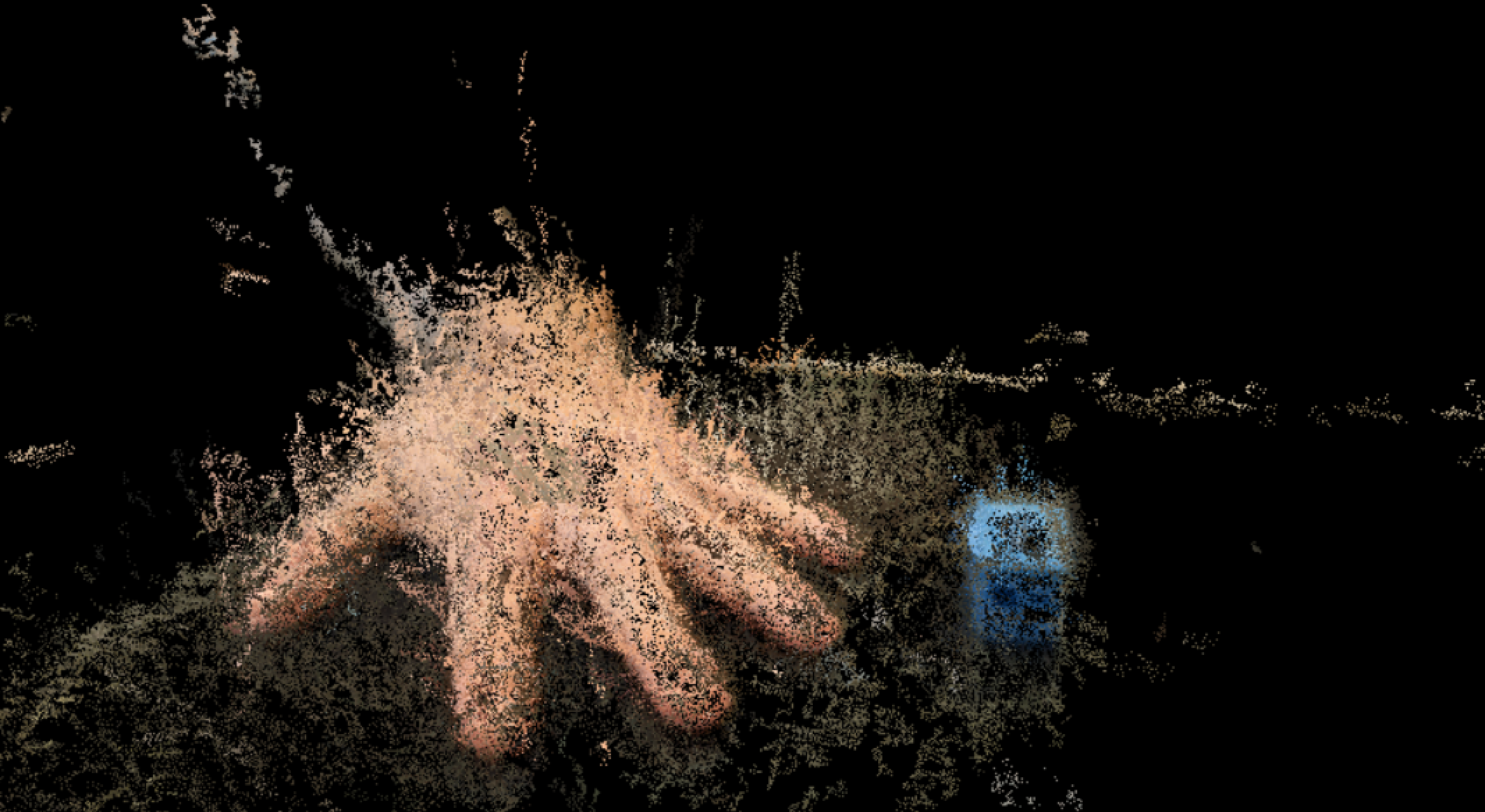
The next step is to generate a dense map. This uses all the known points to generate a more detailed point cloud. This is done by clicking item 4 in the menu. This process will take a really long time with a large number of images, the example here took 80 minutes. Once the process completes, press the TAB key to toggle between the sparse and dense maps.
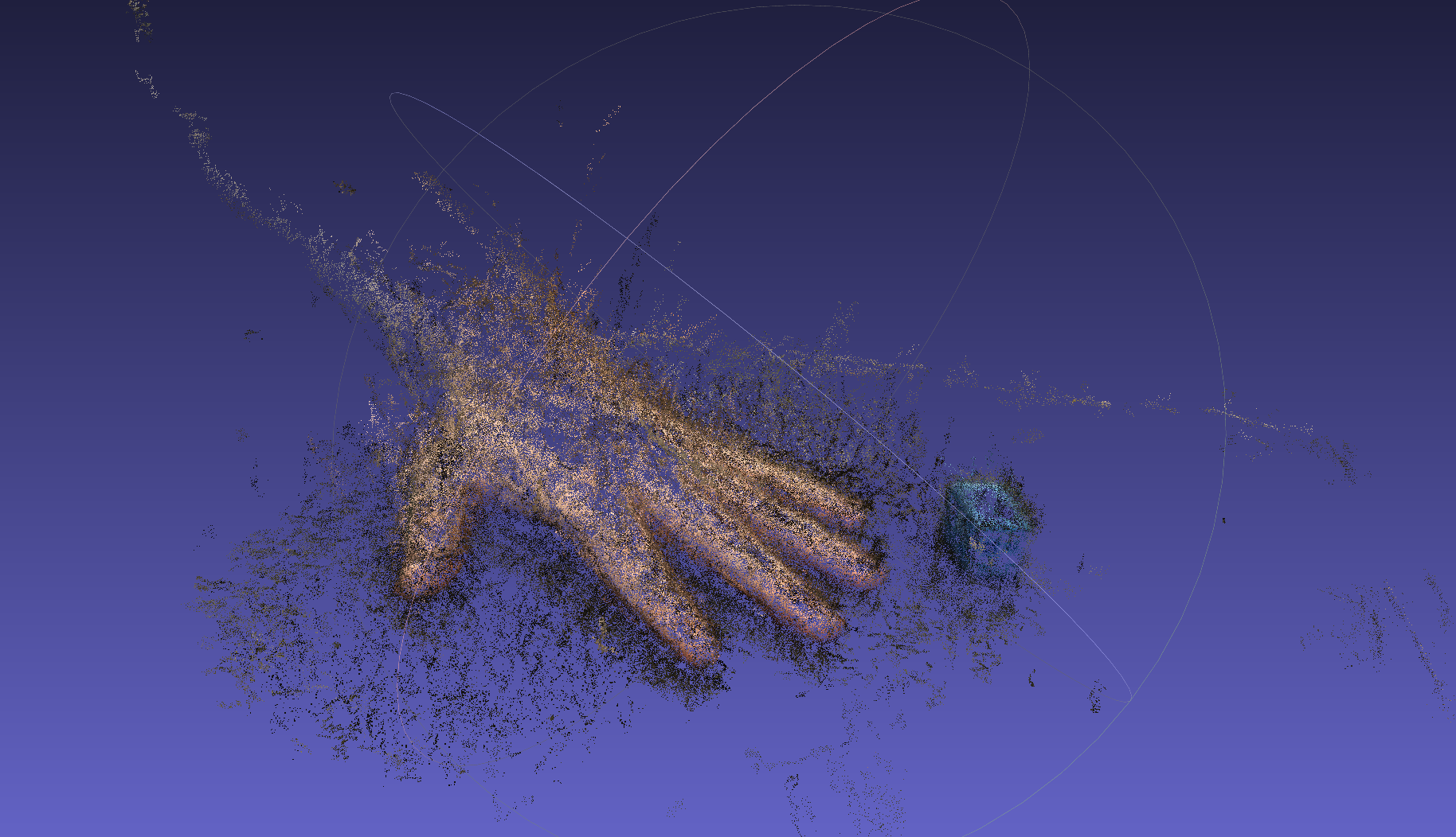
Once the dense reconstruction has occurred on the input images, you will find that a number of extra files will now be accompanying the images in your source folder. These, along with a couple cmvs-output.x.ply files can be used with meshlab to work with the captured object in 3D space.
Simply open the CMVS file in meshlab and you’ll be able to rotate and manipulate the object in 3D.
It became clear even after the inital 20 minute time frame to generate the sparse map that SIFT would not be an optimal solution for HandMap to implement. The reason why it works so well for Curatio is due to the static positioning of the cameras used to capture the object held between them. This static positioning saves a lot of calculation time when generating the maps and mesh as the system knows where it is in relation to its brother and sister cameras.
I do think there is a possible use case for the SIFT method in this project, especially if we can justify offloading some of the mesh processing to a system separate to the users video and photo capturing device. It offers some capabilities of filling in gaps of information when the core system doesn’t function as expected.
Curatio: A Low-Cost & Dedicated 3D Hand Scanner - https://jamesdysonaward.org/projects/curatio-low-cost-dedicated-3d-hand-scanner/
SIFT: Theory and Practice - http://aishack.in/tutorials/sift-scale-invariant-feature-transform-introduction/
VisualSFM : A Visual Structure from Motion System - http://ccwu.me/vsfm/